
Reliable fiber termination is essential for maintaining low optical loss and stable network performance. Instead of installing and polishing a connector directly onto a field cable, technicians often splice the cable to a factory-terminated fiber optic pigtail.
This approach combines the consistency of a factory-installed connector with the reliability of fusion splicing. Fiber pigtails are therefore widely used in telecommunications networks, data centers, FTTH systems, optical distribution frames and industrial fiber installations.
This guide explains what a fiber optic pigtail is, how it differs from a patch cord, the main pigtail types and the factors to consider when selecting one.
A fiber optic pigtail is a short length of optical fiber with a factory-installed connector on one end and exposed, unterminated fiber on the other.
The connectorized end is plugged into an adapter, patch panel or optical device. The unterminated end is usually fusion spliced to an incoming distribution cable, although mechanical splicing may also be used in certain installations.
A typical fiber termination process includes:
Because the connector is installed and polished under controlled factory conditions, a properly manufactured pigtail can provide more consistent optical performance than a connector terminated manually in the field.
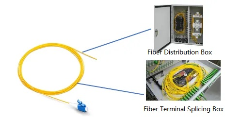
Fiber pigtails are commonly installed wherever permanent fiber cables must be terminated at connector interfaces. Typical applications include:
For example, fibers from an outdoor distribution cable may enter a terminal enclosure and be fusion spliced to SC/APC pigtails. The SC/APC connectors can then be connected to adapters on the front of the enclosure, creating accessible ports for subscriber or equipment connections.
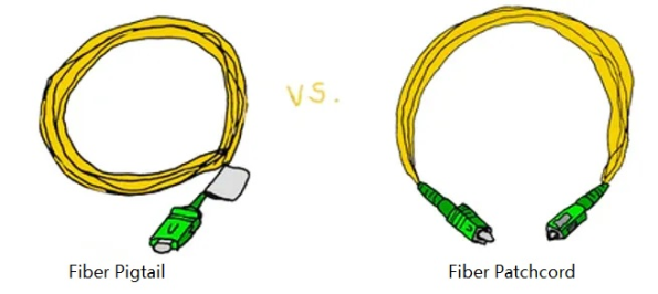
Fiber pigtails and patch cords may use similar fibers and connectors, but they serve different purposes.
| Feature | Fiber Optic Pigtail | Fiber Optic Patch Cord |
|---|---|---|
| Connector configuration | Connector on one end only | Connectors on both ends |
| Opposite end | Bare or unterminated fiber | Factory-terminated connector |
| Primary purpose | Splicing and permanent termination | Connecting two optical ports |
| Typical installation | Inside patch panels, ODFs and terminal boxes | Between equipment, adapters and distribution panels |
| Cable construction | Commonly 0.9 mm buffered fiber; jacketed versions are also available | Usually protected by a 2.0 mm or 3.0 mm outer jacket |
| Installation method | Fusion or mechanical splicing | Direct plug-and-play connection |
A patch cord is intended to connect two connectorized ports. A pigtail is intended to create a connectorized termination by splicing its bare end to another fiber.
Although a duplex patch cord can physically be cut into two connectorized lengths, purpose-built pigtails are generally preferable. They can be supplied with the required buffer construction, stripping length, fiber identification and individual test results.
Fiber pigtails can be classified by fiber mode, connector type, polishing method, cable construction, fiber count and operating environment.
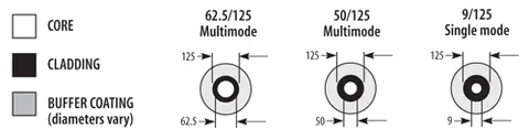
Single-mode pigtails typically use 9/125 μm fiber and are designed for long-distance or high-bandwidth optical transmission.
Common single-mode fiber options include:
Single-mode pigtails are widely used in telecommunications, FTTH, CATV, passive optical networks and long-distance data transmission.
Multimode pigtails use a larger fiber core and are generally selected for shorter transmission distances.
Common multimode categories include:
OM3, OM4 and OM5 pigtails are commonly used in enterprise networks and data centers. The appropriate fiber category should match the installed cable plant, transceiver type, wavelength and transmission-distance requirements.
Fiber optic pigtails are available with a wide range of connector interfaces.
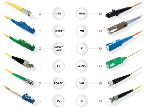
LC connectors use a compact 1.25 mm ferrule. Their small form factor makes them suitable for high-density patch panels, transceivers and data center equipment.
SC connectors use a push-pull coupling mechanism and a 2.5 mm ferrule. They are widely used in telecommunications, FTTH, CATV and general fiber distribution systems.
FC connectors use a threaded coupling mechanism that provides a secure connection. They are commonly found in test equipment, laboratories, measurement systems and applications exposed to vibration.
ST connectors use a bayonet-style coupling mechanism. They remain in use in some industrial networks, legacy telecommunications installations and multimode systems.
E2000 connectors incorporate a protective shutter that helps shield the ferrule from dust and accidental contact. They are used in high-performance telecommunications and optical distribution applications.
Other connector options, including MU, SMA and specialty connector types, may be selected for specific equipment or application requirements.
The connector end-face geometry affects back reflection, return-loss performance and system compatibility.
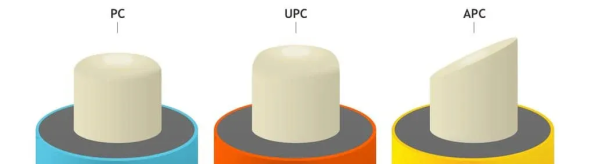
PC means Physical Contact. The ferrule is polished with a slightly curved end face so that the fiber cores make physical contact when two connectors are mated.
PC polish is an earlier physical-contact design and is less common in newly installed single-mode systems than UPC or APC polish.
UPC means Ultra Physical Contact. It uses an improved polishing process to provide better fiber-to-fiber contact and lower back reflection than conventional PC polish.
UPC connectors are commonly used in Ethernet networks, digital transmission systems, test equipment and general telecommunications applications.
APC means Angled Physical Contact. The ferrule end face is typically polished at an angle to direct reflected light away from the fiber core.
APC connectors provide better return-loss performance and are commonly used in:
UPC and APC connectors must not be directly mated. Their end-face geometries are different, and mating them can cause excessive loss, unstable performance and permanent connector damage.
The pigtail construction should match the installation environment and the level of mechanical protection required.
A 0.9 mm pigtail is compact and easy to organize inside splice trays, patch panels and fiber distribution boxes. It is one of the most common constructions for indoor termination.
Jacketed pigtails provide additional mechanical protection and are useful when the fiber is routed outside a protected splice tray or exposed to frequent handling.
Ribbon pigtails contain multiple fibers arranged in a flat ribbon structure. They can support mass fusion splicing and are frequently used in high-fiber-count installations.
Bundle pigtails contain multiple individually buffered fibers grouped together within a common assembly. Each fiber can be routed and spliced separately.
Armored pigtails incorporate a protective metal tube or other reinforcement to resist crushing, pulling and rodent damage. They are suitable for industrial environments or installations requiring increased mechanical protection.
Waterproof pigtails use sealed connectors, reinforced cable structures or outdoor-rated jackets. They are designed for telecommunications towers, outdoor equipment, industrial sites and other harsh environments.
Fiber pigtails may be supplied as individual simplex units or as multi-fiber assemblies.
Common configurations include:
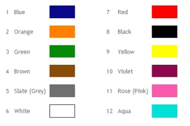
Multi-fiber pigtails should use a consistent color-coding sequence so that individual fibers can be identified correctly during splicing, testing and maintenance.
The connector is installed, polished and tested in a controlled manufacturing environment, helping provide predictable insertion-loss and return-loss performance.
Technicians do not need to install and polish each connector manually. They only need to prepare the fibers, perform the splice and organize the termination.
Fusion splicing creates a permanent, low-loss joint between the incoming cable and the pigtail when the correct splicing procedures are followed.
Pigtails can be customized by fiber type, connector, polish, buffer diameter, jacket material, length, fiber count and color sequence.
Connectorized ports on the front of a patch panel or distribution frame are easier to inspect, clean, test and reconnect than permanently attached bare fibers.
Consider the following factors before ordering.
| Selection Factor | What to Check |
| Fiber mode | Single-mode or multimode |
| Fiber specification | OS2, OM1, OM2, OM3, OM4, OM5 or specialty fiber |
| Connector type | LC, SC, FC, ST, E2000 or another interface |
| Polish type | UPC or APC |
| Cable construction | 0.9 mm buffered, jacketed, ribbon, bundle, armored or waterproof |
| Fiber count | Simplex or multi-fiber assembly |
| Length | Required routing and splice-tray length |
| Jacket material | PVC, LSZH, PE or application-specific material |
| Operating environment | Indoor, outdoor, industrial or harsh environment |
| Test requirements | Insertion loss, return loss, continuity and polarity |
The pigtail fiber should match the transmission fiber being spliced. Mixing incompatible fiber types can increase splice loss and affect network performance.
Connector polish must also match the adapter and mating connector. In particular, UPC and APC interfaces should always remain separate.
Correct installation is as important as selecting the correct pigtail.
For reliable performance:
Contamination is one of the most common causes of optical connection problems. Even a small amount of dust or oil on the connector end face can increase loss or damage the mating connector.
Yes. The connectorized end can be connected to compatible equipment, an adapter or a patch-panel port. The bare end must first be spliced to another optical fiber.
Fusion splicing is the most common method because it provides a permanent and typically low-loss connection. Mechanical splicing may be used when fusion-splicing equipment is unavailable or when the installation requires a removable mechanical joint.
Choose UPC for general digital transmission and standard data-network applications. Choose APC when the system requires improved return-loss performance, such as FTTH, CATV, WDM or analog optical transmission.
The choice must also match the existing adapters and connectors in the network.
Quality pigtails are normally inspected and tested before shipment. Depending on the product and project requirements, testing may include insertion loss, return loss, end-face inspection, continuity and polarity verification.
Fiber optic pigtails provide a practical and reliable method for terminating optical cables inside patch panels, terminal boxes, distribution frames and splice enclosures. By combining a factory-installed connector with a fusion-spliced field connection, they help improve installation consistency, simplify maintenance and reduce the time required for on-site termination.
Selecting the correct pigtail requires more than choosing a connector. Fiber mode, polishing type, cable construction, fiber count, jacket material, installation environment and optical-performance requirements should all be considered.
Sunma supplies configurable fiber optic pigtails with a range of single-mode and multimode fibers, connector types, polish options, cable structures, lengths and fiber counts. Custom configurations and test documentation are available for telecommunications, FTTH, data center, industrial and laboratory applications.

 English Home
 简体中文
简体中文 Online Message
 Skype
Skype
 QQ:20181072

