
Picture this: A technician closes a splice closure after a 12-hour FTTH deployment. The OTDR trace looks clean. The link passes. Three months later, the customer reports intermittent drops that clear themselves before diagnostics can run. The culprit? A pigtail with a 0.08 dB splice that drifted to 0.4 dB because the fiber wasn’t routed correctly in the splice tray, creating a micro-bend under thermal cycling.
This is the paradox of the fiber optic pigtail. It is the shortest cable in your network—typically 0.5 to 2 meters—yet it is the only component that requires permanent fusion splicing, making it irreversible and unforgiving. Unlike patch cords, which can be swapped in seconds, a failed pigtail means reopening an enclosure, re-cleaving, re-fusing, and re-testing. Get it right the first time, and it outlasts the equipment it connects. Get it wrong, and it becomes a latency ghost that haunts your network for years.
This guide treats the pigtail not as a commodity, but as a precision termination system. We will dissect the splicing physics, expose the specification traps invisible to most buyers, and provide a field-proven selection framework.
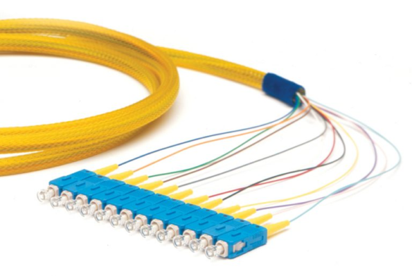
A fiber optic pigtail is a short, tight-buffered optical fiber with a factory-terminated connector on one end and an unterminated bare fiber on the other. The bare end is fusion-spliced to a trunk fiber, creating a permanent, low-loss transition from the field cable to a standard connector interface.
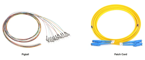
| Attribute | Fiber Pigtail | Fiber Patch Cord |
|---|---|---|
| Termination | One connector; one bare fiber end | Two connectors |
| Connection method | Fusion splice (permanent) | Mating adapter (reversible) |
| Typical IL contribution | 0.05–0.10 dB (splice) + 0.10–0.20 dB (connector) | 0.20–0.50 dB (mated pair) |
| Reusability | Single-use; splice is permanent | Fully reusable; 500–1,000+ mating cycles |
| Primary location | Splice closures, ODFs, FTTH terminals, AI server backplanes | Patch panels, switch-to-switch links, test equipment |
| Loss budget impact | Lower per-connection; ideal for tight budgets | Higher; acceptable where flexibility is required |
Critical Insight: In a 40 km single-mode link with a total loss budget of 28 dB, every 0.1 dB matters. A pigtail with a fusion splice consumes 0.15 dB total. A patch cord through an intermediate adapter consumes 0.40 dB. In high-channel-count DWDM systems, that 0.25 dB difference can be the margin between stable operation and BER (Bit Error Rate) cliffs.
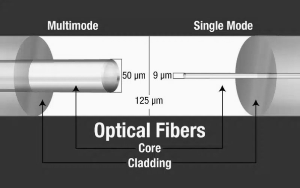
Because pigtails are spliced permanently, the fiber mode decision is irreversible without cutting and re-splicing.
2026 Reality Check: Modern OS2 pigtails increasingly use G.657.A2 bend-insensitive fiber as standard. In crowded splice trays where 12 or 24 fibers must coil within a 30 mm radius, standard G.652.D fiber will develop micro-bending loss. G.657.A2 tolerates 7.5 mm bend radii with <0.1 dB penalty—essential for high-density ODFs and AI cluster trunks.
| Standard | Core | 850 nm BW | 1300 nm BW | 10G Reach | 40/100G Reach | Jacket Color |
|---|---|---|---|---|---|---|
| OM1 | 62.5 µm | 200 MHz·km | 500 MHz·km | 33 m | Unsupported | Orange |
| OM2 | 50 µm | 500 MHz·km | 500 MHz·km | 82 m | Unsupported | Orange |
| OM3 | 50 µm | 2,000 MHz·km | 500 MHz·km | 300 m | 100 m | Aqua |
| OM4 | 50 µm | 4,700 MHz·km | 500 MHz·km | 550 m | 150 m | Aqua |
| OM5 | 50 µm | 28,000 MHz·km (SWDM) | 500 MHz·km | 550 m | 150 m (+ SWDM) | Lime Green |
The OM5 Nuance: OM5 is not merely “faster OM4.” It is engineered for Short-Wavelength Division Multiplexing (SWDM), supporting four simultaneous wavelengths (850/880/910/940 nm) over a single fiber. In pigtail form, OM5 is specified when the trunk is OM5 and the transceiver uses SWDM4 (e.g., 100G-SWDM4). Splicing an OM3 pigtail to an OM5 trunk creates a modal bandwidth bottleneck that nullifies the SWDM investment.
The 62.5 µm Trap: Never splice a 50 µm pigtail (OM2/OM3/OM4/OM5) to a 62.5 µm trunk (OM1). The mode-field diameter mismatch creates a 2–4 dB loss at the junction—enough to kill a 10G link entirely.
The factory-terminated end of a pigtail must match the ecosystem’s reflectance requirements. Unlike patch cords, which can be swapped, a pigtail’s polish type is locked in once spliced.
| Polish | End Face Geometry | Return Loss | Best For | Never Use With |
|---|---|---|---|---|
| UPC | Domed, 0° angle | ≥ 50 dB | Digital Ethernet, data center links, LANs | APC mates |
| APC | Domed, 8° angle | ≥ 60 dB | PON networks, CATV/RFoG, DWDM, analog systems | UPC mates |
Why PON Demands APC: GPON, XGS-PON, and NG-PON2 transmit three wavelengths (1270/1310 nm upstream, 1490/1577 nm downstream) simultaneously. Back-reflection from a UPC connector (−14 dB typical reflection) creates interference in the WDM filters and raises the laser’s relative intensity noise (RIN). The ITU-T G.984 standard explicitly specifies APC at ONT and splitter ports. A green APC pigtail spliced to a trunk in an FTTH terminal box is non-negotiable.
The Color Code: APC connectors are green. UPC connectors are blue (single-mode) or beige/aqua (multimode). This is not branding—it is a safety standard (TIA-598-C). A technician mating a blue UPC adapter to a green APC pigtail will destroy both ferrules and create a permanent high-loss junction.
| Connector | Ferrule | Best For | Pigtail Context |
|---|---|---|---|
| LC | 1.25 mm ceramic | High-density ODFs, SFP/QSFP ports | 144 ports/RU; dominates data center and AI backplane terminations |
| SC | 2.5 mm ceramic | Telecom ODFs, PON splitters, GPON ONTs | Snap-in pull-proof; standard for FTTH and outdoor enclosures |
| FC | 2.5 mm metal | Test equipment, industrial controls, vibration zones | Threaded coupling resists loosening in railway and factory environments |
| ST | 2.5 mm metal | Legacy multimode, industrial Ethernet (PROFINET) | Bayonet twist-lock; declining but still required for retrofits |
| E2000 | 2.5 mm with shutter | Medical, high-power lasers, cleanrooms | Integrated dust cap prevents contamination during unmated storage |
| Configuration | Fiber Count | Typical Use Case | Splice Tray Consideration |
|---|---|---|---|
| Simplex | 1 | FTTH drop, sensor leads, unidirectional video | Minimal; 1 splice sleeve per pigtail |
| Duplex | 2 | Ethernet bi-directional (Tx/Rx), switch uplinks | Requires polarity management (A/B fiber tracking) |
| 4-fiber | 4 | Legacy Token Ring, some industrial buses | Rare in modern deployments |
| 6-fiber | 6 | Small breakout cables, building backbones | Compact ribbon or bunch design |
| 12-fiber | 12 | Data center MPO/MTP breakouts, telecom distribution | Ribbon pigtails enable mass fusion splicing (all 12 fibers in one splice cycle) |
| 24-fiber | 24 | High-density ODFs, 400G/800G parallel optics | Requires large-format splice trays; G.657.A2 bend tolerance critical |
Mass Fusion Splicing: A 12-fiber ribbon pigtail can be spliced to a 12-fiber trunk ribbon in a single automated cycle. A Fujikura 90R mass fusion splicer completes all 12 fibers in ~90 seconds with average losses of 0.05 dB. For a 1,000-fiber data center deployment, this reduces splicing time from weeks to days.
The bare end of the pigtail must be joined to the field fiber. The method chosen determines the link’s long-term stability.
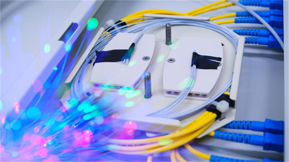
An electric arc melts the cleaved fiber ends together, creating a seamless glass joint.
Field Best Practice: Always verify splice loss with the splicer’s estimated loss reading, then confirm with an OTDR from both ends (bidirectional testing). A splice that reads 0.02 dB in one direction may read 0.08 dB in the reverse due to fiber geometry mismatches (core eccentricity, cladding non-circularity).
An index-matching gel sleeve aligns cleaved fibers under spring pressure.
A pigtail’s total contribution to link loss is:
Total Pigtail Loss = Connector IL + Splice IL + Excess Fiber Loss
| Component | Target | Acceptable Limit |
|---|---|---|
| Factory connector IL | ≤ 0.10 dB | ≤ 0.20 dB |
| Fusion splice IL | ≤ 0.05 dB | ≤ 0.10 dB |
| Mechanical splice IL | ≤ 0.30 dB | ≤ 0.50 dB |
| Total (fusion) | ≤ 0.15 dB | ≤ 0.30 dB |
| Total (mechanical) | ≤ 0.40 dB | ≤ 0.70 dB |
Budget Engineering: In a 10G EPON link with 28 dB total budget, the drop segment might allow only 2.5 dB. If your pigtail+splice consumes 0.3 dB and your splitters consume 14 dB, you have 13.7 dB for the 20 km fiber run. A 0.5 dB pigtail loss would force you to shorten the run by 2.5 km.
| Parameter | Commercial Grade | Industrial Grade | Telecom/Outdoor Grade |
|---|---|---|---|
| Operating temp | -10°C to +60°C | -25°C to +70°C | -40°C to +85°C |
| Storage temp | -20°C to +70°C | -40°C to +85°C | -40°C to +85°C |
| Humidity | 85% RH | 95% RH | 95% RH, condensing |
| Jacket | PVC (OFNR) | LSZH (IEC 60332) | PE/UV-resistant, armored |
The Temperature Trap: Standard acrylate-coated pigtails soften above +85°C. In automotive underhood sensing or oil-well monitoring, specify polyimide-coated fiber rated to +300°C. A standard pigtail in a +120°C enclosure will experience coating creep, shifting the splice point and creating micro-bending loss.

In GPON/XGS-PON deployments, single-mode SC/APC pigtails are spliced to the distribution fiber in the closure, with the connector end plugged into the splitter or ODF. Key requirements:
High-density ODFs use LC/UPC pigtails (or LC/APC if coherent optics are present). In 400G/800G parallel optics:
Factory automation, power grid monitoring, and pipeline sensing use armored or waterproof pigtails:
Calculate total allowable loss from transceiver specifications. Subtract fiber attenuation, splitter loss, and connector losses. The remainder is your pigtail+splice budget. If <0.3 dB, fusion splicing with premium pigtails is mandatory.
| Environment | Jacket | Coating | Notes |
|---|---|---|---|
| Office/data center | LSZH or PVC | Standard acrylate | OFNP for plenum spaces |
| Outdoor telecom | PE, UV-resistant | Standard acrylate | Armored if in conduit with power cables |
| Industrial/factory | Armored TPU | Standard acrylate | Ground armor at one end |
| High-temp (>85°C) | Metal-braided | Polyimide | Oil wells, engine bays |
| Submerged/wet | IP68 gel-filled | Standard acrylate | Marine, manholes |
Insist on factory test reports showing:
The fiber optic pigtail is not a consumable. It is a permanent optical interface that bridges the precision of factory termination with the harsh reality of field installation. Its splice point is invisible once the closure is sealed, making it the highest-stakes connection in the entire link.
The right pigtail preserves your loss budget, eliminates reflection-induced noise, and survives decades of thermal cycling. The wrong pigtail becomes a latent defect—impossible to diagnose remotely, expensive to remediate, and damaging to customer trust.
In an era where 10G PON, 400G data centers, and coherent DWDM define the performance baseline, the pigtail’s 0.15 dB contribution is no longer negligible. It is a system-critical parameter that demands the same engineering rigor as your transceivers, amplifiers, and fiber trunks.
Need pigtails engineered for your specific fusion splicing workflow, environmental envelope, or loss budget? Custom configurations from Fibermart—including G.657.A2 bend-insensitive single-mode, OM5 SWDM-ready multimode, armored industrial assemblies, and pre-polished APC connectors with full interferometry reports—ensure your permanent connections perform like your temporary ones.

 English Home
 简体中文
简体中文 Online Message
 Skype
Skype
 QQ:20181072

