
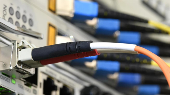
Walk into any modern data center, and you’ll see thousands of them—slender, brightly colored cables snaking between switches, servers, and transceivers. They look interchangeable. They are not.
A fiber jumper (or patch cord) is the final optical link in your network chain. It carries the full weight of your bandwidth promise, yet it is often the most underestimated component in the entire infrastructure. A poorly specified jumper doesn’t just add loss; it creates intermittent failures that take hours to diagnose, introduces reflection points that destabilize coherent transceivers, and becomes the thermal weak point in industrial deployments.
This guide moves beyond the basics. We will dissect the physics, expose the hidden specification traps, and provide a decision framework that prevents your “last mile” from becoming your weakest link.
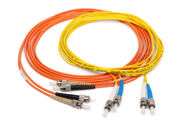
A fiber jumper is a short-length optical cable (typically 0.5 to 10 meters) terminated with precision connectors on both ends. Unlike trunk cables designed for duct installation, jumpers are engineered for dynamic connectivity—they are mated, demated, and rerouted repeatedly throughout their service life.
What separates a commodity patch cord from a network-grade jumper is not the glass itself, but the ferrule geometry, polish quality, and strain relief engineering. In high-speed environments (100G/400G/800G), a jumper with 0.3 dB excess insertion loss can push your link beyond the IEEE 802.3 power budget, triggering automatic shutdown or error-rate spikes.
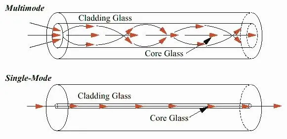
The core diameter dictates how light propagates—and therefore, how far and how fast your data travels.
When to use: Telecom backhaul, coherent DWDM links, 5G fronthaul (>10 km), any application where distance exceeds 550 meters or where laser sources are DFB/EML-based.
Engineering Note: OS2 is not merely “better OS1.” OS2 uses a pure silica core with a depressed cladding design, achieving attenuation as low as 0.18 dB/km at 1550 nm. For links under 2 km, OS1 is perfectly adequate. For spans exceeding 10 km, OS2 is non-negotiable.
Multimode fibers support multiple transverse modes, creating modal dispersion that limits bandwidth-distance product. The “laser-optimized” generations (OM3/OM4/OM5) use a graded-index profile to minimize differential mode delay (DMD).
| Standard | Core | 850 nm BW (MHz·km) | 1300 nm BW (MHz·km) | Typical Reach @ 10G | Typical Reach @ 100G SR10 |
|---|---|---|---|---|---|
| OM1 | 62.5 µm | 200 | 500 | 33 m | Unsupported |
| OM2 | 50 µm | 500 | 500 | 82 m | Unsupported |
| OM3 | 50 µm | 2,000 | 500 | 300 m | 100 m |
| OM4 | 50 µm | 4,700 | 500 | 550 m | 150 m |
| OM5 | 50 µm | 4,700 (953 nm SWDM) | 500 | 550 m | 150 m (supports SWDM4) |
OM5 Nuance: OM5 is not just “faster OM4.” It is optimized for Short-Wavelength Division Multiplexing (SWDM), allowing four wavelengths (850/880/910/940 nm) to be transmitted simultaneously over a single fiber. This quadruples capacity without adding fibers—critical for high-density parallel optics.
When to use MM: Data center intra-rack or inter-rack links (<150 m), 10G/25G/40G/100G SR optics, cost-sensitive campus LANs.
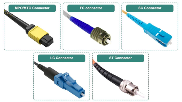
The connector is not merely a mechanical coupler; it is an optical interface that must maintain sub-micron alignment under thermal cycling, vibration, and hundreds of mating cycles.
Why it dominates: At 144 ports per rack unit (RU), LC duplex connectors maximize switch faceplate density. In a 400G QSFP-DD setup, you need 8 fibers per port. LC is the only practical choice for front-panel connectivity.
The APC vs. UPC Decision: SC connectors come in two polish flavors:
Why threads matter: In environments with vibration (railway signaling, wind turbines, factory floors), push-pull connectors can work loose. FC’s threaded coupling maintains constant spring force on the ferrule, ensuring optical stability across -40°C to +85°C thermal swings.
Polarity Trap: MPO cables have three polarity methods (Method A, B, C). A Method A trunk patched with a Method B harness will flip your Tx/Rx pairs, creating a silent failure that optical power meters won’t catch—you need a channel tester or visual fault locator.
The spring-loaded shutter closes automatically upon unmating, preventing ferrule contamination that would otherwise require alcohol wipes and inspection microscopes.
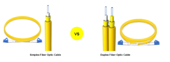
| Configuration | Fiber Count | Typical Use Case |
|---|---|---|
| Simplex | 1 | Unidirectional video, OTDR launch cables, sensor leads |
| Duplex | 2 | Standard Ethernet (Tx/Rx), BiDi optics |
| Ribbon | 8/12/24 | MPO/MTP breakout, parallel optics (SR4/DR4/SR8) |
Critical Detail: In duplex cables, the two fibers are often designated “A” (Tx) and “B” (Rx) with a specific twist in the boot to prevent kinking. Reversing the polarity at one end creates a loopback—your transceiver transmits into its own receiver.
Modern hyperscale data centers operate at 400G per lane and are migrating to 800G. At these speeds, reflectance becomes as critical as insertion loss. A 400G ZR coherent transceiver can tolerate only -26 dB reflectance. A UPC jumper mated to a bulkhead adapter creates a -14 dB reflection point—enough to destabilize the DSP’s phase-locked loop.
Specification checklist for DCs:
5G fronthaul connects RRUs (Remote Radio Units) to BBUs (Baseband Units) over dark fiber. These links often traverse outdoor cabinets, manholes, and tower tops.
Specification checklist:
Factory automation networks (PROFINET, EtherCAT over fiber) face electromagnetic interference from VFDs, welding equipment, and induction heaters. Fiber jumpers eliminate ground loops, but they must survive cable trays shared with 480V power lines.
Specification checklist:
Calculate your total allowable loss:
If your jumper contributes >0.5 dB, you are consuming 1.6% of your entire budget on a 2-meter cable. Specify elite-grade jumpers (≤ 0.10 dB IL) for tight budgets.
Never mix APC and UPC in the same mating pair. The 8° angle on APC creates an air gap when forced against a UPC flat face, resulting in >3 dB loss and potential ferrule damage.
Standard G.652.D fiber has a minimum bend radius of 30 mm. In crowded patch panels, this is often violated. Specify G.657.A2 bend-insensitive fiber, which tolerates 7.5 mm bend radii with <0.1 dB additional loss.
| Material | Flame Rating | Halogen Content | Best For |
|---|---|---|---|
| PVC | OFNR (Riser) | High | General indoor, cost-sensitive |
| LSZH | OFNR/OFNP | None | Ships, subways, hospitals—anywhere human evacuation is a concern |
| OFNP | Plenum | Low | Air handling spaces (HVAC plenums) |
| TPU/Armored | N/A | N/A | Industrial, rodent-prone, outdoor |
Insist on test reports showing:
The fiber jumper is not an afterthought. It is a precision optical component that must preserve the integrity of your link budget, survive your physical environment, and remain stable across thousands of thermal cycles and mating events.
The right jumper does not merely “connect.” It guarantees that the photons leaving your transceiver arrive at the receiver with enough power, enough fidelity, and enough margin to survive the next upgrade cycle. In an era where networks are judged by nanoseconds of latency and 99.999% uptime, the humble patch cord is your first—and last—line of defense.
Need jumpers engineered for your specific link budget, polarity scheme, or environmental envelope? Fibermart provide Custom configurations—including ultra-low-IL elite grade, armored industrial assemblies, and MPO polarity-managed harnesses—ensure your last mile performs like your first.

 English Home
 简体中文
简体中文 Online Message
 Skype
Skype
 QQ:20181072

