
Every time you stream a 4K video, join a video call, or rely on a cloud application, an invisible device is doing one of the most critical jobs in optical networking: splitting a single beam of light into dozens—or even hundreds—of identical signals without amplification, without power, and without failure. That device is the fiber optic splitter.
Once considered a simple passive component, the fiber optic splitter has evolved into a precision-engineered subsystem that directly determines the reach, capacity, and economics of modern Passive Optical Networks (PONs). As 5G fronthaul, 10G-PON, and 25G-PON deployments accelerate, splitter technology is undergoing a quiet revolution. This article explores the engineering behind today’s splitters, the innovations reshaping the market, and what network architects need to know to build future-proof infrastructure.
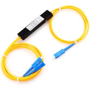
At its core, a fiber optic splitter is a passive waveguide device that divides an incoming optical signal into multiple output paths with a fixed power ratio. Unlike active switches or routers, splitters require no electrical power, generate no heat, and have no moving parts—making them exceptionally reliable for “fit and forget” deployments.
They are the foundational building blocks of PON architectures, where a single Optical Line Terminal (OLT) at the central office serves dozens of Optical Network Units (ONUs) at customer premises. Without splitters, fiber-to-the-home (FTTH) would be economically impossible.
| Parameter | FBT (Fused Biconical Taper) | PLC (Planar Lightwave Circuit) |
|---|---|---|
| Technology | Two fibers fused and tapered under heat | Lithographically etched silica waveguides on a chip |
| Splitting Ratios | 1×2, 1×4 (rarely higher) | 1×2 up to 1×128 (and 2×N variants) |
| Insertion Loss (1×32) | Not feasible | ~17.0 dB typical |
| Wavelength Dependence | High (>6 dB variation across 1260–1650 nm) | Low (<0.5 dB across C+L bands) |
| Temperature Stability | Moderate (-5°C to +75°C) | Excellent (-40°C to +85°C) |
| Cost (1×8) | Lower | Higher, but scales better at 1×32+ |
| Current Market Share | Declining (~15%) | Dominant (~85%) |
The verdict is clear: While FBT splitters still find niche use in simple 1×2 couplers and custom ratio applications, PLC technology has become the industry standard for PON networks due to its superior uniformity, wavelength-flat response, and scalability to high splitting ratios.
The global FTTH subscriber base surpassed 1.1 billion in 2025, and 5G networks require dense fiber connectivity to thousands of small cells. This is driving demand for 1×64 and 1×128 PLC splitters that were once considered exotic.
However, splitting light 128 ways comes with physical constraints. Each doubling of ports adds ~3 dB of theoretical insertion loss. A 1×128 splitter therefore exhibits minimum loss of ~21 dB, plus manufacturing tolerances. This pushes the optical power budget to its limits, demanding:
Market impact: Vendors like Corning, Broadex, and Tianyisc are now shipping 1×128 splitters with typical insertion loss below 17.5 dB and uniformity better than 1.2 dB—specifications that would have been laboratory-grade just five years ago.
Traditional splitters are “dumb” power dividers: they treat all wavelengths identically. But modern networks are increasingly wavelength-aware. Two developments are changing this:
WDM-PON (Wavelength Division Multiplexing PON): Instead of splitting a single wavelength to 32 users, WDM-PON assigns a unique wavelength to each ONU. This requires arrayed waveguide gratings (AWGs)—essentially wavelength-selective splitters that route λ₁ to port 1, λ₂ to port 2, and so on. AWGs function as both splitters and demultiplexers, enabling symmetric 10 Gbps per user without the bandwidth-sharing penalty of TDM-PON.
Coexistence Elements: As networks migrate from GPON (1490 nm) to XGS-PON (1577 nm) to NG-PON2 (TWDM at 1596–1603 nm), operators need splitters that can handle multiple wavelengths simultaneously without crosstalk. Modern PLC splitters are now qualified for the full 1260–1650 nm range, with polarization-dependent loss (PDL) held below 0.2 dB across all channels.
The integration of splitters with Photonic Integrated Circuits (PICs) represents the most significant architectural shift since the move from FBT to PLC.
Instead of a standalone splitter spliced into a fiber network, PIC-based solutions embed the splitter alongside lasers, modulators, detectors, and multiplexers on a single silicon or indium phosphide chip. This delivers:
Real-world example: Intel’s silicon photonics transceivers integrate a 1×4 splitter with four germanium photodetectors on a single die, enabling 400G DR4 optical modules in a QSFP-DD package. In telecom, Infinera’s ICE6 coherent engine uses PIC-integrated splitters to distribute local oscillator power across multiple receiver channels.
The biggest limitation of passive splitters has always been their opacity: once installed in a closure or handhole, they offer no visibility into their own health. That is changing with fiber Bragg grating (FBG)-enabled splitters and micro-optical tap monitors.
These capabilities are critical for automated fiber management systems and digital twin implementations, where the physical layer must be as observable as the IP layer.
As fiber density increases—particularly in 5G macro sites and hyperscale data centers—splitter packaging is evolving rapidly:
| Package Type | Typical Size | Use Case |
|---|---|---|
| Bare PLC chip | 3 mm × 20 mm × 1 mm | Inside transceivers and PICs |
| Mini steel tube | Φ3.0 mm × 54 mm | Fiber splice trays, tight spaces |
| ABS box module | 100 mm × 60 mm × 12 mm | Standard FTTH closures |
| LGX/19″ rack cassette | 1U, SC/LC adapterized | Data center and central office |
| High-density MPO cassette | 1U, 144 fibers | Hyperscale DC spine-leaf |
Emerging trend:Rollable/flexible PLC splitters using thin-film lithium niobate or polymer waveguides are entering R&D pipelines, promising splitters that can conform to curved surfaces inside aircraft, vehicles, and wearable medical devices.
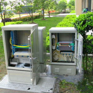
In a typical GPON deployment, a 1×32 splitter sits in a street cabinet, dividing a 2.488 Gbps downstream signal among 32 homes. The splitter’s uniformity determines whether the farthest ONU receives enough power to maintain a stable link. A poorly manufactured splitter with ±3 dB variation can leave edge users with intermittent service, while a ±1 dB unit ensures consistent performance.
5G networks use eCPRI (enhanced Common Public Radio Interface) over fiber to connect baseband units (BBUs) to remote radio units (RRUs). Here, 1×6 or 1×12 splitters distribute signals from a centralized BBU hotel to multiple cell towers. The splitters must operate across a wide temperature range (-40°C to +70°C for outdoor cabinets) and maintain low PDL to prevent signal degradation in coherent detection systems.
Inside data centers, 1×2 and 1×4 splitters are used for optical tap modules that feed network monitoring and security tools (NDR platforms, packet brokers). These require ultra-low insertion loss (<3.5 dB for 1×2) to avoid impacting production traffic, and broadband performance to support both 1310 nm (multimode) and 1550 nm (single-mode) links.
When procuring fiber optic splitters, these parameters separate commodity-grade from carrier-grade quality:
| Parameter | Why It Matters | Carrier-Grade Target |
|---|---|---|
| Insertion Loss (IL) | Directly reduces optical power budget | Add ~0.5 dB to theoretical minimum |
| Return Loss (RL) | Reflections cause laser instability and noise | >55 dB (APC connectors) |
| Polarization-Dependent Loss (PDL) | Critical for coherent and high-speed systems | <0.2 dB |
| Uniformity | Ensures equal performance across all ports | <1.5 dB for 1×32, <2.0 dB for 1×64 |
| Directivity | Prevents crosstalk between output ports | >55 dB |
| Operating Temperature | Reliability in outdoor/uncontrolled environments | -40°C to +85°C |
| Wavelength Range | Future-proofing for multi-wavelength systems | 1260–1650 nm (full O-to-L band) |
Pro tip: Always request IL and uniformity test data per port from the manufacturer, not just “typical” values. A splitter that meets average specs but has one outlier port can create a “ghost fault” that takes days to diagnose.
The next frontier in splitter technology is reconfigurability. Research labs and startups are developing:
While these technologies remain 3–5 years from mass deployment, they signal a fundamental shift: the passive splitter is becoming an intelligent, software-defined network element.
Fibermart Fiber optic splitters may lack the glamour of 400G transceivers or AI-powered network controllers, but they are arguably more consequential. They are the economic fulcrum of FTTH, the density enabler of 5G, and the reliability anchor of PON architectures.
As splitting ratios climb, wavelengths multiply, and integration with silicon photonics accelerates, the humble splitter is proving that passive components can drive active innovation. For network architects and procurement teams, the message is clear: investing in high-quality splitter technology today is investing in the scalability and resilience of your network for the next decade.
The light has already left the laser. Whether it reaches its destination efficiently, reliably, and economically depends on what happens inside that small silica chip.

 English Home
 简体中文
简体中文 Online Message
 Skype
Skype
 QQ:20181072

